Step 5 of HybridV2- Hybrid Control Unit
##Control Unit
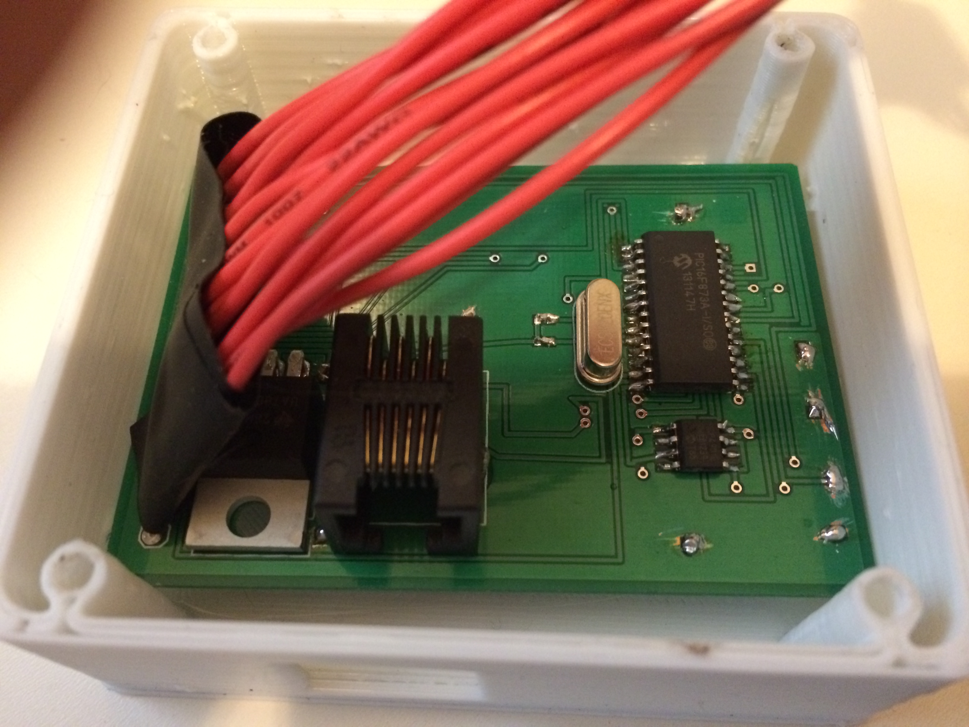
The control unit is made up of a PIC16F873A Microchip microcontroller along with a few other passive units for taking inputs and driving outputs. There are obviously no off the shelf units which could perform this job completely; however, the unit most likely could have used other popular microcontroller units ranging from the arduino to the raspberry pi. But considering some of the requirements for the input and output, the custom unit does an altogether better job.

Hybrid Unit

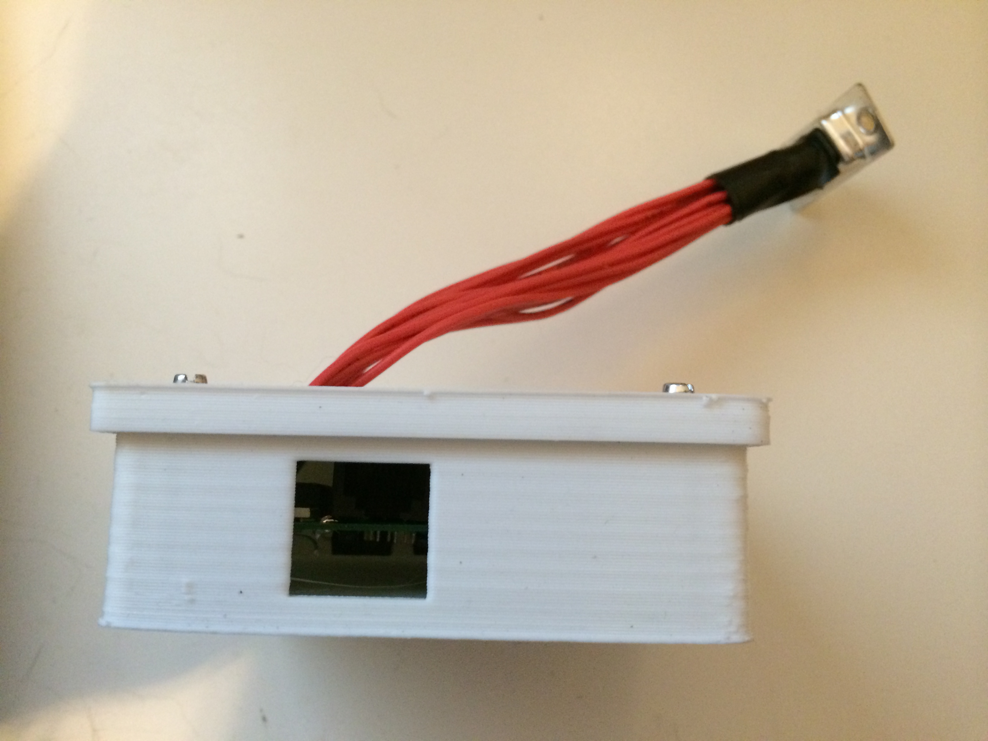
Hybrid Unit in Case
The electrical connections to the unit are through the DB-15 connector. The debug connection is supplied through the usual ( for microchip) RJ connector. The casing is a 3d printed box which is secured inside the under seat section, right next to the supercapacitors.
###Inputs
- Hall Input
- In order to measure the speed of the bike, one of the hall sensor outputs of the motor is tapped and lead to the unit. By measuring the frequency of the 5V train the speed of the bike is measured. This is more easily accomplished by using the Capture Command Peripheral ( CCP) section of the microcontroller which implements an in hardware PWM comparator.
- Analog Throttle Input
- As discussed in the Step 2 Post, the hybrid unit takes in the analog throttle output from the user. This signal is captured and analyzed by one of the units A/D converters.
- Algorithm Switch
- There is also a switch on the unit in order to toggle between different algorithm designs. As will be discussed in testing, it is helpful to have multiple algorithms and the ability in testing to switch between them.
###Outputs
- ICE Throttle Output
- The ICE is controlled via a Hobby Servo which is bolted to the throttle body. It is controlled via a digital output pin on the microchip.
- Brake Switch Output
- The brake output switch is a simple digital signal sent to the electric motor controller and is driven using a standard npn - pnp transistor gate.
- Electric Controller Output
- The electric controller acceleration and brake analog signals are generated off of digital signals from the microchip which are converted to analog in a D/A converter on the board but separate from the microcontroller.
- Contactor Output
- The contactor for the high voltage system is operated by the hybrid unit. This allows the unit to only connect the system when all checks are complete and to also disconnect if there is a problem. Because of the higher current involved in driving this, it is driven off a digital i/o pin with a higher current transistor.
- Meter Output
- The voltage meter output, on the speedo, is also driven off a stepped reference of the high voltage which is divided from the hybrid unit.