Step 3 of HybridV2- Mechanical
##Electric Movement
In version 1 of the hybrid I had used a AC Motor. While the performance was great and the mounting and transmission was easy, it took up a surprising amount of room in the overall design. With a platform like the Honda Metropolitan, there was simply no room. Instead, the electric motor is a BLDC hub motor, manufactured for electric mopeds. In Beijin specifically, these electric mopeds with a twenty mph top speed seem quite popular. Specifically its the 60V 3KW hub motor sold here. A more powerful motor would have been preferable; however, it was the highest output unit I could find that maintained the Metropolitans 13 inch wheel size. If there are other units which do the trick, please email the link.
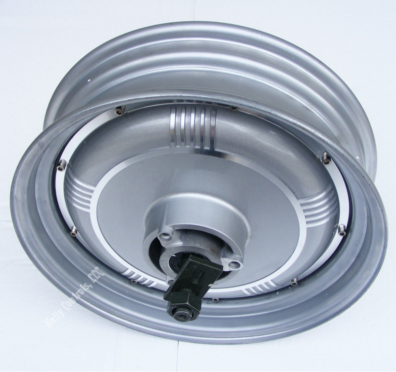
BLDC Electric Hub Motor
All in all it is not a horrible choice, although there are three things which definitely need improvement for future versions. Firstly it is very heavy, because it contains a ring of neodymium magnets mounted in its steel ring, it all adds up to a significant increase in weight.
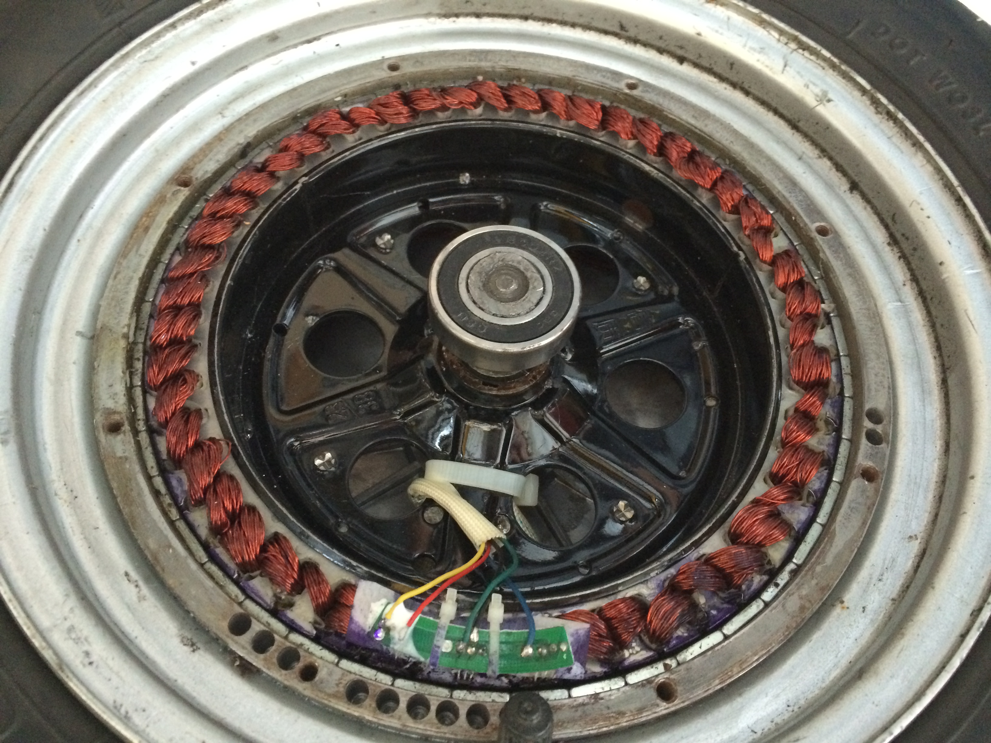
Inside Hub Motor
Secondly, in combination with the electric controller the output voltage for regeneration and acceleration is limited to a range of speed from 0-25 mph-ish. Which means that when up at speed, the electric power for accelerations is mostly useless. Lastly, while the physical stresses on the unit are certainly different than what was imagined by the engineers, the unit has already suffered from one bearing failure after less than a thousand miles.
##Transmission and Mounting
The standard Honda Metropolitan, much like all 50cc scooters, has a integrated motor and CVT transmission unit. This presents two problems for the integration of the hub motor. First, the wheel has no bearings, the bearings are integrated into the trans unit. Secondly, the transmission ends at the center of the bike, and the wheel is thin enough to stay in the center of the bike, the hub motor is much wider and if there were a way of bolting the unit on, the wheel would be offset by about six inches.
Example of 50cc motor/trans unit
First step to integrate the units is to offset the transmission by the six inches required. This is accomplished with a crankshaft adapter which moves the engine see of the transmission the required six inches. In addition, six inch spacers are used to separate the transmission from the engine. The required pieces were custom made.
Custom Transmission Piece
Engine Spacing
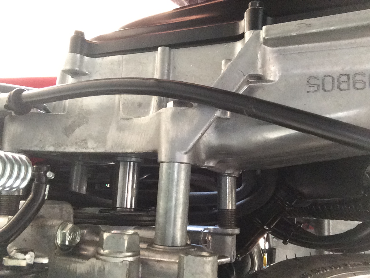
The second step is to modify the hub motor, by removing the axle on the transmission side. After removing the axle, a brake adapter manufactured for mounting custom wheels was bolted first to the transmission and then bolted to the hub motor.
Hub Motor Connection with visible Engine/Trans Gap
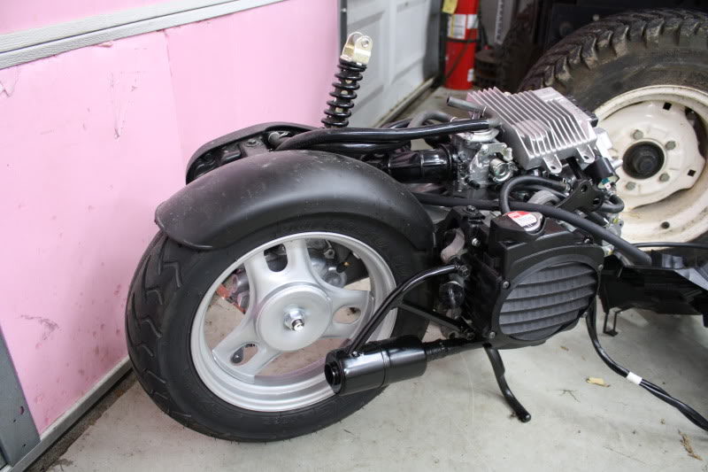
Hub Motor Mounted
The opposite side of the hub motor from the transmission is mounted on a channel three inch section of aluminum 6061 which is bolted one side to the axle of the hub motor and the other side to the engine. This adds strength and rigidity to the hub motor.
comments powered by Disqus